How NeoPixels Work
Ever wondered how NeoPixels work? Let’s take a look at two examples: the WS2812B and SK6812, and how they can be used to create a chain of individually addressable RGB LEDs.
Images captured using a LINKMICRO LM249MS
Introduction
NeoPixels are a type of individually addressable RGB LED that can be used to create a chain of LEDs that can be controlled by a single microcontroller pin. They are available in a variety of form factors, including strips, rings, and matrices.
They are commonly used in projects such as LED cubes, and can be used to create a wide variety of lighting effects.
WS2812B vs SK6812
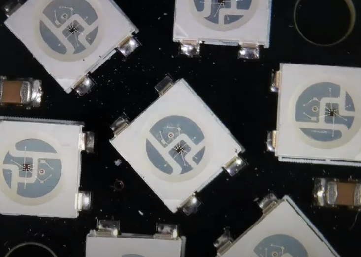
These are both popular NeoPixels that are available in a variety of form factors: 3535 and 5050 surface mount package. These packages are then either sold individually or in strips, rings, and matrices.
Note: If you’re not familiar with the concept of packages, you can think of it as the size of the component. For example, a 5050 SMD (surface mounted) package is a 5mm x 5mm component that is mounted on a PCB, and similarly a 3535 surface mount package is 3.5mm x 3.5mm.
Both are 4-pin devices, with a power pin, ground pin, data input pin, and data output pin. The data input pin is connected to the data output pin of the previous device in the chain, and the data output pin is connected to the data input pin of the next device in the chain.
The data signal specifies for each NeoPixel in the chain the RGB (and sometimes W depending on the device) values that should be set by each of the controllers. The data signal is passed through the device to the next device in the chain.
There are a few differences between SK6812 and WS2812B:
- SK6812 has a wider color range, including RGB, RGBW, WWA, and single white. But WS2812B is usually only RGB.
- Compared with WS2812B, SK6812 has almost no voltage drop.
How NeoPixels are assembled
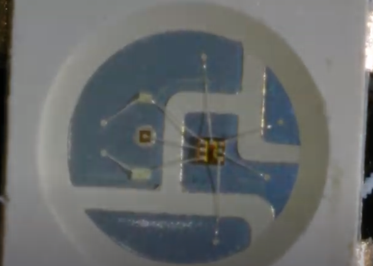
NeoPixels are assembled by machine. An empty PCB is positioned within reach of an arm which places the controller and each of the LEDs on the board. The LEDs and controller IC (chip) are then connected to the controller using bond wires.
We can see this if we take a look at the WS2812B under a microscope:
 The WS2812B under a 240X microscope
 The WS2812B under a 720X microscope
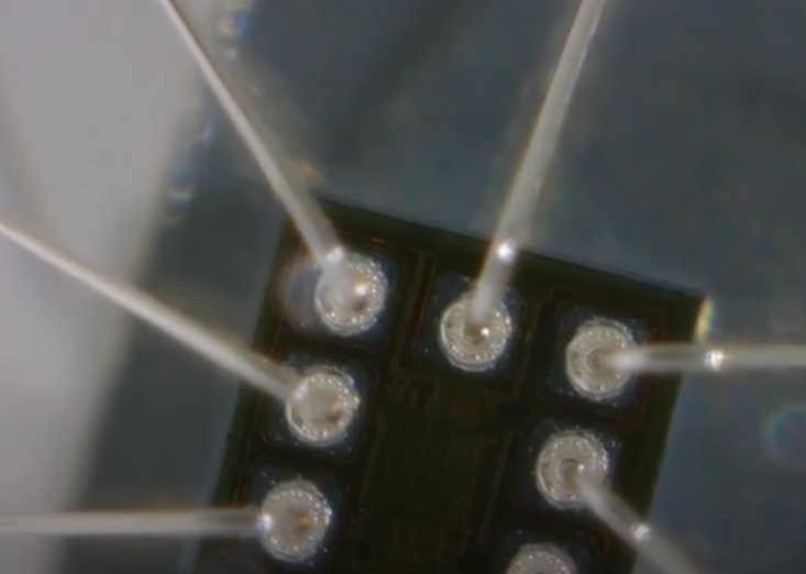 The WS2812B under a 2040X microscope
The wires that connect the components are only 20 microns thick (1/5th the width of a human hair), and are difficult to see with the naked eye. Despite this the precise machine can place over 30,000 wires an hour!
If you’re interested in the assembly process in more detail, the YouTube channel Strange Parts has a great video explaining the detail in this video:
Using NeoPixels in your own circuits
If you are planning to use NeoPixels in your own circuits, you may need to include decoupling capacitors next to each NeoPixel. These are often included in the PCB or LED strip, but if you are creating your own PCB you may need to include them yourself.
A 100nF ceramic capacitor is recommended, and should be placed as close as possible to the NeoPixel.
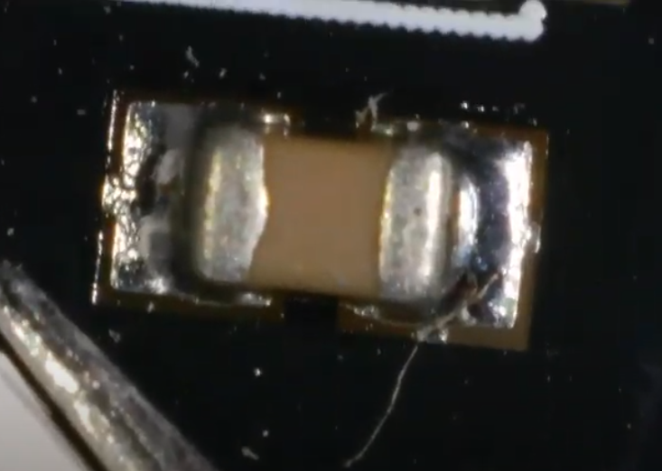 The decoupling capacitor on the board alongside the WS2812B
Connecting NeoPixels to an Arduino (or Raspberry Pi)
NeoPixels can be connected to an Arduino using a single pin. The data pin of the first NeoPixel in the chain is connected to the Arduino, and the data output pin of the first NeoPixel is connected to the data input pin of the second NeoPixel, and so on.
The NeoPixels are typically powered by 5V pin, if you are using a lot of NeoPixels you should connect them directly to a power source, rather than via the microcontroller’s 5V pin. This is because the microcontroller may not be able to supply enough current to power all of the NeoPixels.
Don’t forget to join the ground of the power supply to the ground of the Arduino.
A note about Raspberry Pi
If you’re connecting to a Raspberry Pi there are a couple of things you need to be aware of:
The voltage level is different, a Raspberry Pi uses 3.3V logic, so you will need to use a level shifter or NeoPixel driver module to convert the 3.3V logic to 5V logic.
You need to disable audio on the Raspberry Pi. This is because the hardware PWM feature of the Raspberry Pi has to be manipulated by the software library, but this is also used by the sound driver. You can do this by adding
dtparam=audio=offto/boot/config.txt. If you’d like to avoid this because you’re using audio, you can buy an I2C to NeoPixel controller to control the NeoPixels via I2C instead.