Connecting Modules to the ESP32
I have been working with the Arduino and Raspberry Pi for a few years now, but I have only recently started to explore the ESP32. I have been impressed with the capabilities of the ESP32, and I have been experimenting with a few different modules to see what I can do with them.
The ESP32 is a powerful microcontroller that has built-in WiFi and Bluetooth capabilities. This makes it ideal for IoT projects, as it can connect to the internet and communicate with other devices wirelessly. Unfortunately it isn’t as simple to work with as some of the other microcontroller dev boards, so I wanted to share some of the things I have learned so far.
Interfaces
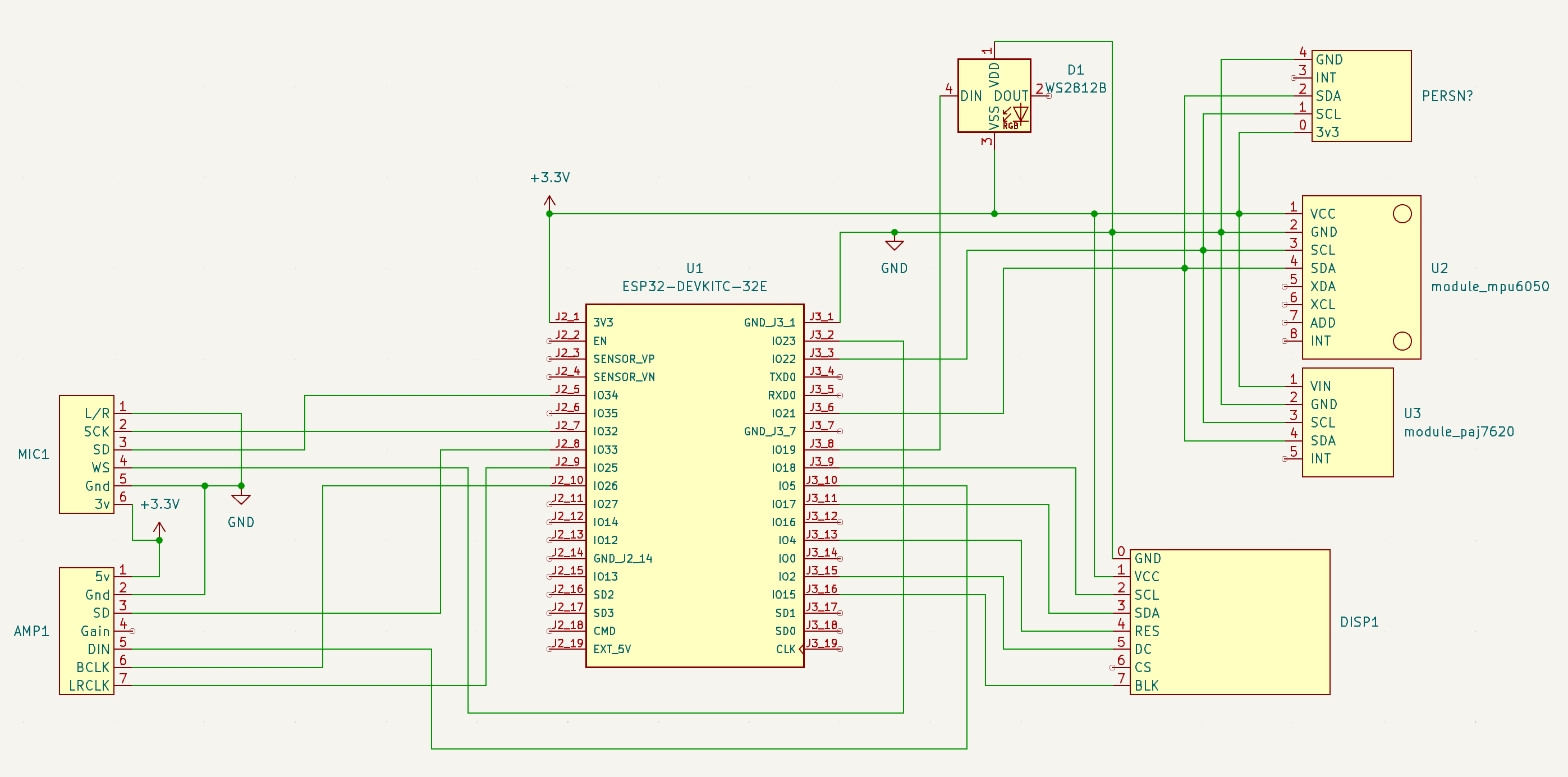
There are a number of interfaces that are typically used to connect modules to the ESP32. Let’s take a look at the most common ones:
- GPIO: General Purpose Input/Output pins are the most common way to connect modules to the ESP32. These pins can be used for digital input or output, and can also be used for analog input or output with the use of an ADC or DAC.
- I2C: Inter-Integrated Circuit is a two-wire serial bus that is commonly used to connect sensors and other modules to microcontrollers. The ESP32 has two I2C buses, which can be used to connect multiple devices.
- SPI: Serial Peripheral Interface is a synchronous serial communication interface that is commonly used to connect devices like displays, SD cards, and other peripherals to microcontrollers. The ESP32 has two SPI buses, which can be used to connect multiple devices.
- I2S: Inter-IC Sound is a serial bus that is commonly used to connect audio devices to microcontrollers. The ESP32 has two I2S buses, which can be used to connect audio devices like microphones and speakers.
GPIO
This is the more simple of the interfaces to use, as it is just a digital pin that can be set to input or output. Most of the pins are avaible to use as a GPIO, but there are some, such as the ones used for the flash memory, that are not available.
For more information take a look at this GPIO reference where you can see GPIO 6 to 11 are used for the integrated SPI flash.
In some development boards these are not broken out, but others have them available, so be careful.
I2C
I2C is a two-wire serial bus that is commonly used to connect sensors and other modules to microcontrollers. The ESP32 has two I2C buses, which can be used to connect multiple devices.
Typically I2C requires 4 pins:
- VCC (3.3V)
- GND
- SDA (Data)
- SCL (Clock)
Multiple devices can be connected to a single I2C bus, as long as they have different addresses. This is usually set by a jumper or solder bridge on the module if it is available to set.
For more information in I2C addresses take a look at this complete guide to i2c.
SPI
SPI is a synchronous serial communication interface that is commonly used to connect devices like displays, SD cards, and other peripherals to microcontrollers. The ESP32 has two SPI buses, which can be used to connect multiple devices.
Typically SPI requires the following pins:
- VCC (3.3V)
- GND
- MOSI (Master Out Slave In):
- MISO (Master In Slave Out)
- SCK (Clock)
- CS (Chip Select)
Chip Select is used to select the device you want to communicate with by setting high or low when multiple SPI devices are connected to the same bus.
There are specific pins for the available SPI busses:
| SPI | MOSI | MISO | CLK | CS |
|---|---|---|---|---|
| VSPI | GPIO 23 | GPIO 19 | GPIO 18 | GPIO 5 |
| HSPI | GPIO 13 | GPIO 12 | GPIO 14 | GPIO 15 |
Some devices (such as the display modules ST7789 or GA9A01) have additional pins for the backlight or touch screen. They may also have the CS pin grounded internally so you don’t need to connect it.
- RES (Reset)
- DC (Data/Command)
- BL (Backlight)
Example: ST7789 display
Here is an example of how to connect an ST7789 display to the ESP32:
| SPI PIN | ST7789 LABEL | ESP32 PIN | Notes |
|---|---|---|---|
| VCC | VCC | 3.3V | |
| GND | GND | GND | |
| SCLK | SCK / SCL | GPIO 18 | Clock |
| MOSI | SDA / DIN | GPIO 23 | Data |
| MISO | N/A | N/A | Not used |
| CS | N/A | N/A | Grounded internally |
| - | DC | GPIO 2 | Data/Command |
| - | RES / RST | GPIO 4 | Reset |
| - | BLK | 3.3V / GND | Ground to disable |
I2S
Probably the most confusing of the interfaces I have been working with, I2S allows you to connect audio devices to the ESP32. This is a serial bus that is used to transmit audio data between devices.
Typically I2S requires the following pins:
- VCC (3.3V)
- GND
- BCLK (Bit Clock)
- LRCLK (Left/Right Clock)
- DATA (Data)
- MCLK (Master Clock)
Also you may have the following pins depending on the device:
- LRSEL or L/R (Left/Right Select): For stereo audio
- SCLK or SCK (Serial Clock): Serial-Data Clock
- WS (Word Select): Serial Data Word Select
- GAIN: For devices that have an amplifier
- SD: allows you to mute the output on the MAX98357A amplifier, and on the INMP441 mems mic, it is used to output the data.
The pins can be set in code to use any of the available pins, but my testing has shown the following will work:
INMP441 MEMS microphone
| I2S PIN | INMP441 LABEL | ESP32 PIN | Notes |
|---|---|---|---|
| VCC | VCC | 3.3V | |
| GND | GND | GND | |
| WS | WS | GPIO 23 | Word Select |
| SD | SD | GPIO 34 | Serial Data |
| SCK | SCK | GPIO 32 | Serial Clock |
MAX98357A amplifier
| I2S PIN | MAX98357A LABEL | ESP32 PIN | Notes |
|---|---|---|---|
| VCC | VCC | 3.3V | |
| GND | GND | GND | |
| DOUT | DIN | GPIO 5 | Data Input to amplifier |
| BCLK | BCLK | GPIO 26 | Bit Clock |
| LRC | LRC | GPIO 25 | Left/Right Clock |
| GAIN | GAIN | N/A | Amplifier gain control |
| SD | SD | 33 | Mute control (optional) |
Gain can be controlled as followed reference:
- 15dB if a 100K resistor is connected between GAIN and GND
- 12dB if GAIN is connected directly to GND
- 9dB if GAIN is not connected to anything (this is the default)
- 6dB if GAIN is connected directly to Vin
- 3dB if a 100K resistor is connected between GAIN and Vin
Code examples
We have examples of the code for use with the modules in this guide in the GitHub repository:
Help contribute
I’m always looking to improve the information in this article, so if you have any suggestions or corrections, please let me know in the discord community