BL4825O - The Missing Datasheet
As this was my first foray into the world of brushless DC motors (BLDC) I decided what better way to start than to find the cheapest motor possible without any documentation…
Introduction
The BL4825O brushless DC motor is sold on AliExpress via the link below, and includes the technical details below. Besides this there is very little in the way of technical specifications, wiring diagrams or any other guides. So this is the closest you’re likely to get.
Technical Spec
Item
BL4825O Mini 48mm Brushless Motor DC12V 14.4V 24V 4000RPM Large Torque Reversible PWM Speed Regulation BLDC Motor For Fascial gun
Specification
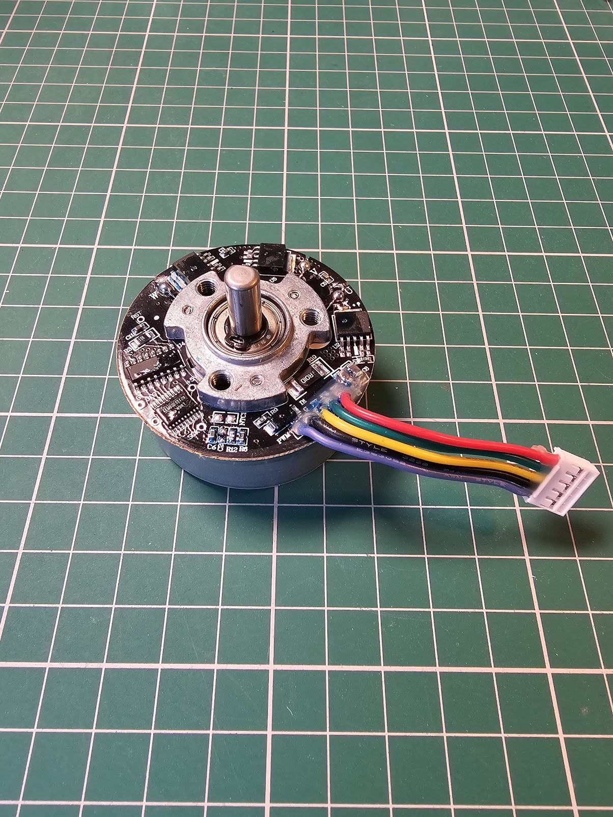
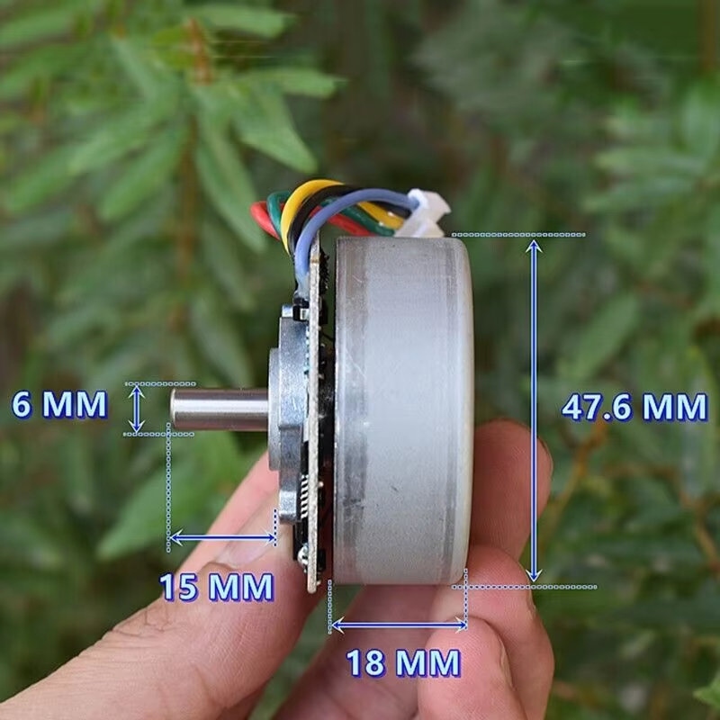
The outer rotor brushless motor with a drive plate is a brushless motor with a membrane gun, a rare earth medium strength magnetic brushless motor, with an outer diameter of 47.6mm, a model of 4825O, and a rated voltage of DC24V 4000 rpm.
It supports PWM signal speed regulation. If the PWM signal is connected to the negative pole, the motor will run at the highest speed, so that it can operate normally with only one set of DC power sources.
The definition of wiring is as follows:
Red line: positive pole
Green line: FG (feedback signal line, suspended without wiring)
Yellow line: direction line, turning to CCW when connected to negative pole, turning to CW when suspended
Black line: Common GNd (negative pole of power supply+PWM negative pole)
Blue line: PWM (if connected to the negative pole, the motor runs at maximum speed)
The yellow line is the direction line, but if the motor cannot switch between forward and reverse directions during operation, it is necessary to select the motor’s steering direction when the motor is stationary. If the motor is running, immediately changing the steering direction is invalid. The blue line is also a PWM line, and the input PWM signal has a duty cycle of 0% -100% to regulate speed. The ground wire of the PWM signal line should also be connected to the black line. If the PWM signal wire (blue wire) is directly connected to the black wire, the motor will run at maximum speed.
Motor weight: 168 grams
This motor can operate normally at DC12V-24V. If the red wire is connected to the positive pole, and the black and blue wires are connected to the negative pole, the motor will operate at the highest speed.
Voltage: DC12V No load current: 0.12 A Maximum speed: 1980 rpm
Voltage: DC18V No load current: 0.14 A Maximum speed: 3000 rpm
Voltage: DC24V No load current: 0.16 A Maximum speed: 4000 rpm
If a PWM signal is input on the blue line and the negative pole of the PWM signal is also connected to the black line, then adjusting the duty cycle can adjust the speed.
The following measured rotational speeds with different duty ratios (voltage DC24V):
- 0% 3980RPM 0.16 A
- 20% 3750RPM 0.15 A
- 40% 3000RPM 0.12 A
- 60% 2380RPM 0.11 A
- 80% 1680RPM 0.07 A
- 99% 770 RPM 0.04 A
Note: The positive and negative poles of a brushless motor are strictly prohibited from being connected in reverse. The red wire is connected to the positive pole, and the black wire is connected to the negative pole. If connected incorrectly, it will burn out the drive board
Hardware
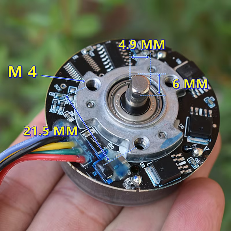
The motor’s spindle and rear section are connected meaning that the both spin, the control board is the only section that does not, so you need to mount it to something with M4 bolts prior to testing otherwise you may find it difficult to work with.
Arduino Wiring
To connect to an arduino, use the following connections.
Note that the motor needs at least 12v so you should connect the arduino to a separate 5v power source and link the ground pins.
| Motor Wire | Arduino Pin | Notes |
|---|---|---|
| Green FG | A0 | Feedback pin (see code example) |
| Yellow | 8 | Direction of rotation |
| Blue | 9 | PWM to set speed |
| Red | N/A | Connect to 12-24v DC |
| Black | Black | Link grounds between motor, arduino and power source |
The arduino pins can be changed as required, this example is purely because I used this configuration when testing.
Example Code
1
2
3
4
5
6
7
8
9
10
11
12
13
14
15
16
17
18
19
20
21
22
23
24
25
26
27
28
29
30
31
32
33
34
35
36
37
38
39
40
int pwmPin = 9;    // PWM connected to digital pin 9
int dirPin = 8;     // Direction
int feedback = A0;

int delayVal = 100;
int maxVal = 255; // If this isn't 255 it won't stop.
int minVal = 50; // Lower = faster

unsigned long duration;

void setup() {
  Serial.begin(115200);
  pinMode(dirPin, OUTPUT);
  pinMode(feedback, INPUT);
}

void loop()
{
  // fade in from min to max in increments of 5 points:
  for (int fadeValue = minVal ; fadeValue <= maxVal; fadeValue += 5) {
    // sets the value (range from 0 to 255):
    analogWrite(pwmPin, fadeValue);
    //Serial.println(digitalRead(feedback));
    // wait for 30 milliseconds to see the dimming effect
    duration = pulseIn(feedback, HIGH);
    Serial.println(duration);
    delay(delayVal);
  }
  delay(2000);
  // fade out from max to min in increments of 5 points:
  for (int fadeValue = maxVal ; fadeValue >= minVal; fadeValue -= 5) {
    // sets the value (range from 0 to 255):
    analogWrite(pwmPin, fadeValue);
    //Serial.println(digitalRead(feedback));
    // wait for 30 milliseconds to see the dimming effect
    duration = pulseIn(feedback, HIGH);
    Serial.println(duration);
    delay(delayVal);
  }
}
Feedback Pin Output
When running the above script you should see the output on the serial plotter similar to the screenshot below. This will allow you to monitor the status of the motor.
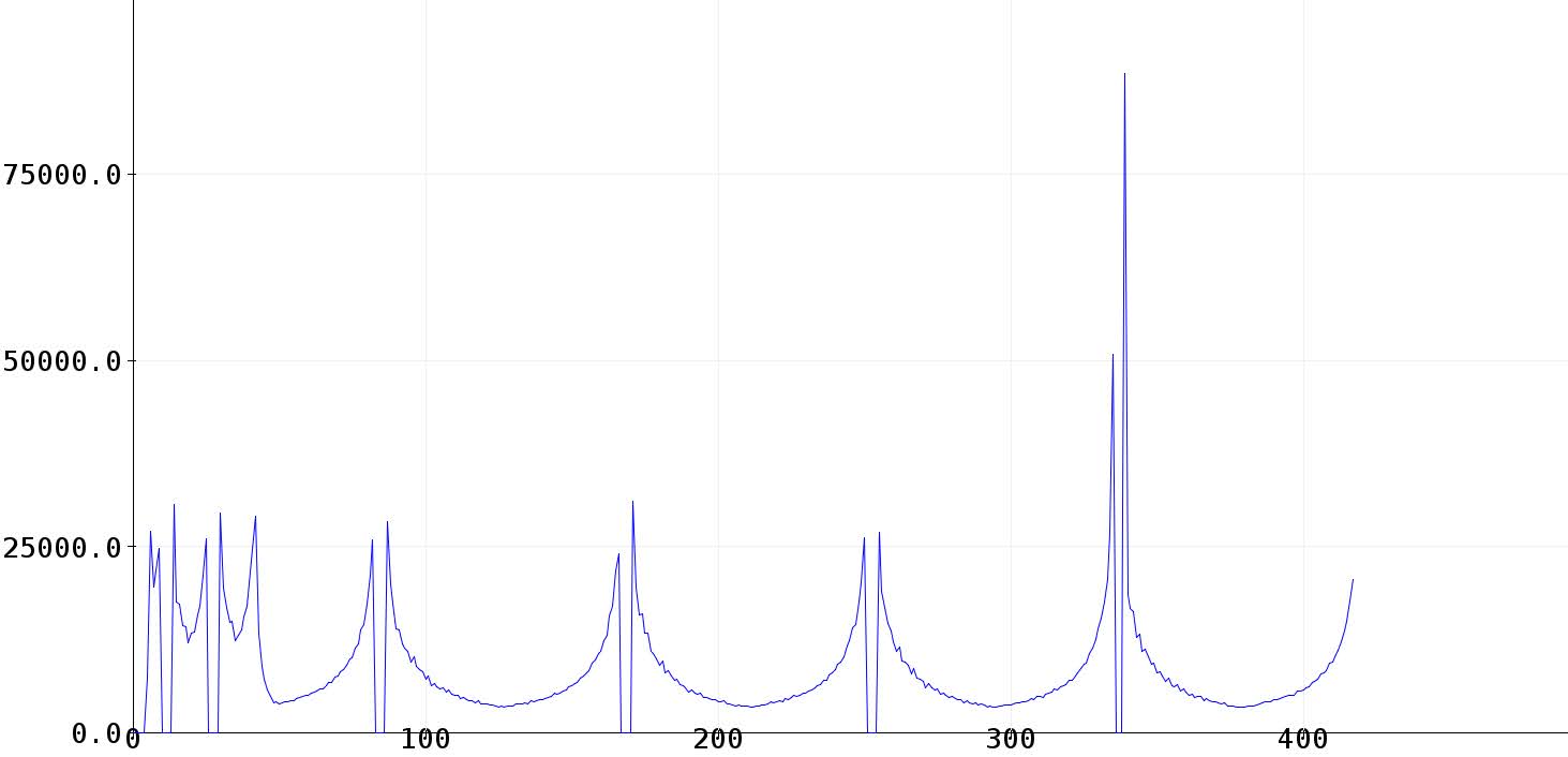
This utilises the pulseIn() method to measure the pulses sent by the motor controller.