Biped Servo Calibration Made Easy
In the last update of the Modular Biped Framework I redesigned and rebuilt the legs to allow for a greater range of motion on the knee joint. Now I want to re-calibrate the legs to take advantage of the new hardware.
The legs are controlled by an Arduino Pro Mini in the body which is running a piece of code, called a sketch, that tracks the servo positions and also manages the minimum and maximum range of motion on each servo.
Tracking the range is critical, because if a servo were to over-extend then it would impact another part of the model which would cause damage to either the servo or the leg itself.
More complex robots that self-calibrate typically have limit switches installed, so that when the end of the range of motion is reached the switch is triggered and it prevents over-extension, but this design doesn’t have those switches in place, so it needs to be calibrated manually by storing the minimum and maximum positions.
The positions are stored in arrays in the sketch, and these need to be reset every time a design is changed.
Previously, calibrating these servos involved making changes to the values manually and uploading the sketch again to the arduino. The problem is that this is a very lengthy process and not fun to iterate with.
For this reason, I have recently added a calibration action to the sketch. To enable this, just jump into the Config.h file and uncomment this define.
#define SERVO_CALIBRATION_ENABLED
This will override the default behaviour and allow you to enter a loop in the serial monitor, that looks something like this.
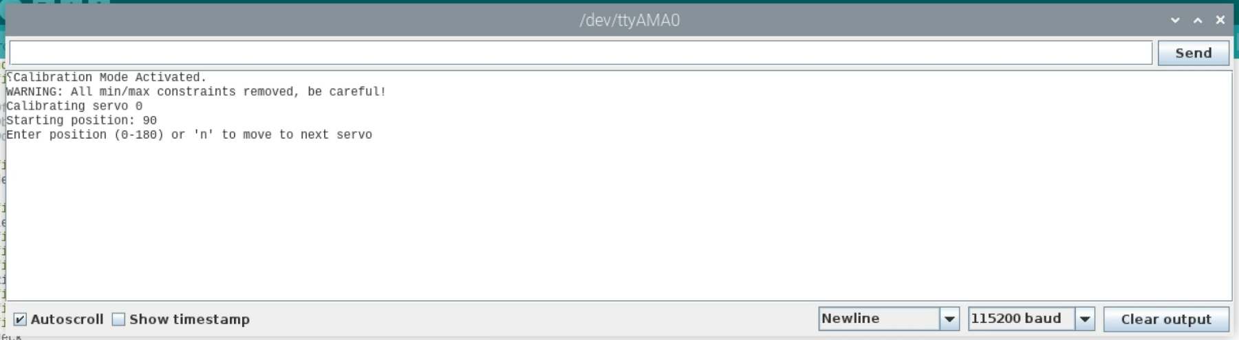
The loop first moves the servos to the 90 degree position to help with manual alignment. I’d recommend that you start the script without the gears attached to the servos, then add the gears with the legs manually positioned at the mid-point in the range of each servo.
The exception to that may be the knee, where you may find you need to set the servo position to 0 (or 180 for the opposite leg) and then attach the gear once the leg is in the most closed position possible.
The script will iterate through each of the servos and allow you to manually control the rotation angle. Just enter a value between 0 and 180 and hit return.
Once you’re happy with the servo position, hit return without entering a value. This will move to the next servo.
Once all the servos have been set the script will output the values for each so that you can copy them into the sketch. It then begins the loop again.
The values aren’t stored in the code, so make sure you copy and paste them into the appropriate array once you’re done, to save them permanently.
A quick warning here: Normally there is a safety feature enabled in the servo management library so that you can’t over-extend the servos, but in calibration mode this safety feature is disabled, so you can quite easily damage the hardware if you aren’t careful!
ServoEasing::ServoEasingArray[i]->setMinMaxConstraint(0, 180);
Symmetric Movement
Setting each servo individually is useful for defining the minimum and maximum values in the range of motion, but to define different poses on the leg you may want to set the values on one leg and have the other leg mirror that position. In order to enable this, go back to Config.h and enable the define to allow symmetric calibration.
#define SERVO_CALIBRATION_SYMMETRICAL
Once deployed, you can adjust the individual joints on one leg, and you’ll see that the other leg is automatically calculated to mirror the position.
Next Steps
There is also a balancing algorithm in place using the MPU6050 to adjust the position of the body, and inverse kinematics to calculate the leg position once they have been calibrated. If you’re interested in either of these, take a look at the code. Link in the description.
If you would like to build the robot yourself, you can find links below to the files and code. Everything is open source. Also feel free to reach out on the discord server if you have questions.